While attempting to improve the physical interface to the Tapuino I thought about Rotary Encoders which I've wanted to experiment with for a while. I managed to obtain some locally for a fairly reasonable price and set about looking for a solid code base to use. There seem to be a huge number of libraries and as many complaints about the quality of these libraries. Eventually I stumbled across this blog post which promised:
Rotary encoders, done properly
The premise looked really promising: a simple state machine for matching encoder state transitions and some lightweight code. Unfortunately the library behaved rather oddly. The first step was always missed and transitioning from one direction to another would also miss a step. Looking at the code it seemed that the state transition table was incorrect in some way, but for the life of me I couldn't reverse engineer the logic as the transitions seemed counter intuitive.
I decided to recreate the table from first principles so that I would completely understand the logic behind the idea and ended up with a solution that seems to work without error which I will explain below.
Firstly some basic theory. Rotary encoders generally have two output pins and a common pin.
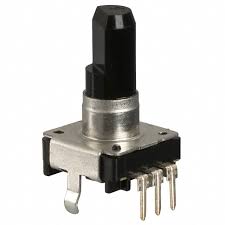 |
| Mechanical Rotary Encoder, center pin is common. |
As the shaft is rotated the pins are switched on and off in a specific sequence. For example, rotating the shaft clockwise produces the following output:
| Output Stage | Pin A | Pin B |
|---|
| 0 | 0 | 0 |
| 1 | 1 | 0 |
| 2 | 1 | 1 |
| 3 | 0 | 1 |
| 4 | 0 | 0 |
The first and last entries are when the encoder is at rest. Each set of outputs is one 'click' in an encoder with 'dedents'. When rotated in the counter clockwise direction the code is reversed:
| Output Stage | Pin A | Pin B |
|---|
| 0 | 0 | 0 |
| 1 | 0 | 1 |
| 2 | 1 | 1 |
| 3 | 1 | 0 |
| 4 | 0 | 0 |
You can get more detail on this
Wikipedia article under the section "Incremental rotary encoder". The theory from the post mentioned above was to build a state machine to map these states. In the post the author describes a state machine with seven possible states and gives each a value. Each state name maps to an output state in the tables above. The states and values in the original code are:
| R_START | 0x0 |
| R_CW_FINAL | 0x1 |
| R_CW_BEGIN | 0x2 |
| R_CW_NEXT | 0x3 |
| R_CCW_BEGIN | 0x4 |
| R_CCW_FINAL | 0x5 |
| R_CCW_NEXT | 0x6 |
Where: R_START is the common 0-0 value and used as a beginning and ending state, R_CW_BEGIN would map to the 1-0 output state, R_CW_NEXT to the 1-1 output state, R_CW_FINAL to the 0-1 output stage and so on. While the value of the states is arbitrary, I chose to change the values so that they followed a 'logical' order:
| R_START | 0x0 |
| R_CW_BEGIN | 0x1 |
| R_CW_NEXT | 0x2 |
| R_CW_FINAL | 0x3 |
| R_CCW_BEGIN | 0x4 |
| R_CCW_NEXT | 0x5 |
| R_CCW_FINAL | 0x6 |
The code then goes on to read the state of pins A and B and computes a combined pin state as:
value = A << 1 | B
In other words the combined pin state can have the binary values 00, 01, 10, 11 or decimal 0, 1, 2, 3. This pin state is then used to perform a transition in a state table. The original state table looks like this:
const unsigned char ttable[7][4] = {
  // R_START
  {R_START,    R_CW_BEGIN,  R_CCW_BEGIN, R_START},
  // R_CW_FINAL
  {R_CW_NEXT,  R_START,     R_CW_FINAL,  R_START | DIR_CW},
  // R_CW_BEGIN
  {R_CW_NEXT,  R_CW_BEGIN,  R_START,     R_START},
  // R_CW_NEXT
  {R_CW_NEXT,  R_CW_BEGIN,  R_CW_FINAL,  R_START},
  // R_CCW_BEGIN
  {R_CCW_NEXT, R_START,     R_CCW_BEGIN, R_START},
  // R_CCW_FINAL
  {R_CCW_NEXT, R_CCW_FINAL, R_START,     R_START | DIR_CCW},
  // R_CCW_NEXT
  {R_CCW_NEXT, R_CCW_FINAL, R_CCW_BEGIN, R_START},
};
The current state is the row in the table and the combined pin state is used to find a column in the table indicating the next state to transition to. The code that does this looks like this:
state = ttable[state & 0xf][pinstate];
The DIR_CW and DIR_CCW values are OR'd into the state to signal that a transition has occurred. So at starting state R_START with pin values 1-0 (the first set of values in a clockwise transition) the table above would transition to R_CCW_BEGIN....
And I'm not sure how that is supposed to be correct. Lets find out what the correct values should be by mapping this out. Here is a basic table describing the state machine. States as rows and transitions as columns:
 |
| Basic Layout |
The next step is to realise that if we are in a state and we read the same pin values that got us into this state, we should
stay in the state:
 |
| Transitioning back to the same state |
So, if we are in R_START and read 0-0 we should transition back to R-START, similarly if we are in R_CW_BEGIN and read 1-0 we should transition back to R_CW_BEGIN. With this out of the way, we can map out the transitions for clockwise:
 |
| Clockwise direction state map added |
Here in sequence:
- State = R_START, pins read 1-0, transition to R_CW_BEGIN (row 1, column 3)
- State = R_CW_BEGIN, pins read 1-1, transition to R_CW_NEXT (row 2, column 4)
- State = R_CW_NEXT, pins read 0-1, transition to R_CW_FINAL (row 3, column 2)
- State = R_CW_FINAL, pins read 0-0, transition to R_START (row 4, column 1)
At the point of the final transition, the pattern has been matched and we should emit a Clockwise Event.
Similarly we can map out the transitions for counter clockwise:
 |
| Direction 2 state map added |
Here in sequence:
- State = R_START, pins read 0-1, transition to R_CCW_BEGIN (row 1, column 1)
- State = R_CCW_BEGIN, pins read 1-1, transition to R_CCW_NEXT (row 5, column 4)
- State = R_CCW_NEXT, pins read 1-0, transition to R_CW_FINAL (row 6, column 3)
- State = R_CCW_FINAL, pins read 0-0, transition to R_START (row 7, column 1)
At the point of the final transition, the pattern has been matched and we should emit a Counter Clockwise Event.
So now that we've mapped out the two complete transitions there is only one thing left to do. All of the blank entries in the table map out illegal states. If we find an illegal state all we need to do is transition back to R_START so that the next legal set of pin inputs can be followed:
 |
| Error state map added |
|
In code this would look like this:
unsigned char ttable[7][4] = {

  {R_START, R_CCW_BEGIN, R_CW_BEGIN,  R_START},

  {R_START, R_START,     R_CW_BEGIN,  R_CW_NEXT},

  {R_START, R_CW_FINAL,  R_START,     R_CW_NEXT},

  {R_START, R_CW_FINAL,  R_START,     R_START},

  {R_START, R_CCW_BEGIN, R_START,     R_CCW_NEXT},

  {R_START, R_START,     R_CCW_FINAL, R_CCW_NEXT},

  {R_START, R_START,     R_CCW_FINAL, R_START},

};
Adding in the flags to indicate the final state transitions then becomes extremely logical:
ttable[R_CW_FINAL][R_START] |= DIR_CW;
ttable[R_CCW_FINAL][R_START] |= DIR_CCW;
"When in the final state and transitioning to the start state, emit the direction"
Well this was really interesting to figure out and I hope it helps some folk out there. Now I need to implement this code into the Tapuino...
Till next time, hack on!
-(e)


